


Pumps are firmly and permanently entered our everyday life. The capabilities and capabilities of these units allow solving problems with the pumping pressure in the water supply network. It does not matter which pump is the pump or the self-priming pump station. The main thing is to correctly choose the pump by its characteristics and connect it yourself.
Content
The construction of the boosting water pump
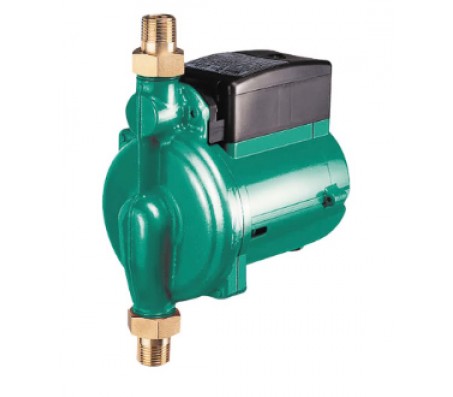
Modern household units pumps are sophisticated devices designed for pressure transfer of liquid working medium. The problem of raising the pressure in the water mains and the subsequent transportation of water is decided by the boost pumps, which are a monoblock design of the main elements "pump-motor".

Structurally, the boost pump consists of elements:
- a heat-insulating casing of the housing with a threaded connection, open on one side
- single-phase or three-phase rotary electric motor
- spherical rotor on shaft with impeller
- check and check valves
- plug connector
- flow sensor
- thermostat.

Booster pumps of industrial production are produced in cast-iron casings with anti-corrosion coating or steel casings.
The water pump is an electrical device equipped with a thermal protective relay and a capacitor. The unit is connected to standard machines in accordance with the parameters of the motor.

Principle of operation, circuit and device
The principle of operation and the scheme of the boost pump are based on the ability to create a radial flow of water by the impeller and transfer of kinetic energy to the converted pressure energy. Models of boost pumps for water supply operate on an identical principle and are installed on the main cold or hot water supply systems.
specifications
The main characteristics of boost pumps are:
- performance and maximum head
- consumed power and maximum working pressure
- permissible t of the pumped liquid and its maximum flow rate
- noise level from the unit in working order.
In addition, when installing the boost pump it is recommended to pay attention to the parameters:
- overall dimensions of the unit, type of installation installation, length and size of the threaded connection (pipe connection G 3/4 ", 1/2" and HP connection).
The pump of the boost pump and its operating conditions depend on the control method, which are divided into automatic and manual control.

Helpful Tips
Theoretically, the pressure of the working medium in the water pipes of multi-storey buildings is regulated and ranges from 1.5 to 4 Atm. However, a violation of the rules for installing household plumbing fixtures lowers the pressure head to critical values of 1-1.3 Atm. To find out what an increase pump for heating or water supply of an apartment or house will be able to do is recommended from the performance diagrams and from here
flow sensor
An important element of the units is the flow sensor, designed to automatically turn on / off the pump motor, made of brass with the possibility of connecting ½ choke - ¾ nut, with two output contacts for switching the load of the motor 220V / 120W. The units of the boost pump grundfos are equipped with an integrated flow sensor, which eliminates the need for additional equipment connection. However, it does not exclude the need to calculate the pump.

Calculation of the boost pump
When calculating the pump, it is recommended to use the raw data - the supply (load) of the maximum water consumption and the pressure, determined by the difference in pressure between the specified inlet and pressure at the water inlet.
The pressure at the input is defined as the sum of the excess pressure at the upper point of the draw-off (5-10 m.v.st.) and the head loss in the "upper point - boost pump" section.

Calculate the pump is recommended using on line calculator. As a result of the calculation, taking into account the loss of pressure along the entire length of the water pipe, local losses and the coefficient. losses at fittings, loss of pressure on the meter will receive peak water consumption. Based on the calculated characteristics, we select a pump from the diagram, capable of providing the required head.

Helpful Tips
Calculation of the characteristics of the pump is mandatory and is confirmed by the practice of installing the instruments. The design characteristics are a key parameter for the subsequent installation and electrical connection. Do not belittle the reliability of the calculated part of the characteristics. We will suggest that additional purchase and installation of a storage tank and a pump with a pressure switch are considered a reliable option for connecting an up-pump.

All useful information about the design of the boost pump is shown here.
Technology, scheme and method of connection
Booster pumps are considered small-sized devices placed directly on the trunk pipe of an apartment or a private house. We can not hide that the pump is only able to increase slightly, not once, to increase pressure, ensuring better circulation of the water carrier.
The technology and scheme of the boost pump is simple. Moreover, in the kit to the pump from the manufacturer there is an investment of necessary adapters and fittings.

Stages of installation and connection
- We make a marking of the pipe for connection in accordance with the length of the device and the adapters.
- We overlap the water supply.
- According to the markings, we cut off the water pipe.
- At the ends of the water pipe we cut the external thread.
- On the cut off pipe screwed adapters (vnutr.rezba).

We screw the fittings according to the flow direction marking with arrows on the pump casing.
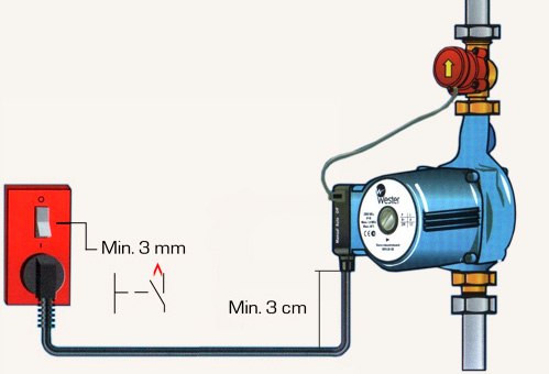
Electrotechnical connection is made according to the scheme declared by the manufacturer.


